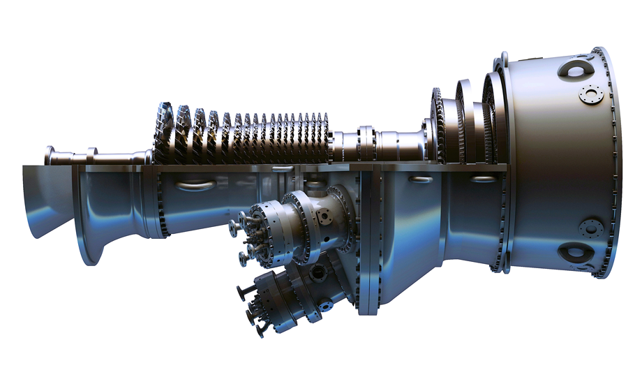
6F.03 (6FA) gas turbine unit

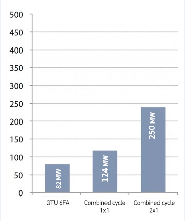
Specifications of power units based on gas turbine units 6F.03 (6FA)
| GT MODEL | Simple cycle
output power | 1х1
Combined cycle output power | 2х1
Combined cycle output power | Efficiency in the combined cycle |
| 6F.03 (6FA) | 82 MW | 124 MW | 250 MW | >55% |

Maintenance
Russian Gas Turbines LLC provides for a full range of maintenance services, including the services of installation/adjustment supervision, efficiency tests, personnel training, as well as services of long-term maintenance.

International operation experience
The 6F.03 (6FA) gas turbine is well-suited for both base load and cyclic duty in a variety of configurations, including combined cycle, district heating, oil and gas or industrial cogeneration.
Main technical parameters and key components
The gas turbine unit 6F.03 (6FA) is based on the advanced technologies used in GT 7FA design. The configuration is a single shaft, bolted rotor with the generator connected to the gas turbine through a reduction gear coupling on the compressor side or on the "cold" end. Such feature allows for axial exhaust and arrangement optimization in the combined cycle.
Gas turbine 6F.03 (6FA) parameters
| PARAMETER | VALUE |
|---|---|
| Number of compressor stages | 18 |
| Compression ratio | 16.4:1 |
| Number of turbine stages | 3 |
| Combustion chamber type, number of combustion chambers | cannular, 6 combustion chambers |
| Fuel combustion temperature | > 1260 °C |
| Fuel types | Natural gas, associated petroleum gas, synthetic gas, diesel fuel |
| Starter | Electric motor |
| Exhaust system | Axial |
6F.03 (6FA) gas turbine generator parameters
| PARAMETER | VALUE |
|---|---|
| Power (delay) coefficient |
0.8 |
| Output voltage, kV | 11.5 kV |
| Rated power, MW | 82 MW |
Compressor
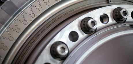
Compressor is axial and has 18 stages with the first row of modulating inlet guide vanes and a compression ratio of 16.4:1 under ISO conditions. Compressor consists of rotor and casing (stator). The first two stages are realized with supersonic technologies. Compressor is designed with interstage air extraction for cooling and sealing of the turbine nozzles and the wheel space, as well as for surge control during GT start-up. Compressor wheels are tightened with 15 bolts, thus making a rigid structure, and are centered with rabbets.Combustion system
The gas turbine has a reverse-flow system with six low-emission combustion chambers of the 2nd generation (DLN-2.6), with six nozzles per chamber. Standard combustion system equipment includes two retractable spark plugs and four flame detectors. Crossfire tubes connect each combustion chamber to adjacent chambers on two sides. Heat-resistant insulation is applied to the internal surface of liners and transition pieces. Each combustion chamber, flame tube or adapter can be replaced separately to facilitate maintenance.Casings and exhaust diffusor
The gas turbine has five casings that are horizontally split for maintenance and repair. Boroscopic holes are located on compressor casing, combustion chambers and turbine casing for visual inspections. Fire-resistant bearing can be accessed by removing the upper half of the compressor inlet casing. The other bearing is readily accessible for maintenance and repair without dismantling the turbine casing.Exhaust diffusor consists of two cylinders. After the third turbine stage, exhaust gases flow to the diffusor, where they slow down and restore pressure to improve efficiency. The exhaust diffusor is equipped with 21 thermocouples to control gas temperature.
Turbine
Turbine section has three stages with air cooling of all three nozzle stages and of the first two bucket stages. The first-stage bucket has an advanced cooling system to bear high combustion temperatures. The cooling system uses turbulated inner passages with cooling air discharging through the blade tip, front and back edges. Blades have elongated shanks to isolate turbine wheel rim from hot gas flow, and integral shrouds are incorporated on the 2nd and 3rd stages to eliminate fatigue stresses and to improve efficiency. The first stage has a two-piece shroud that allows reducing tip clearances.The design of a single-shaft rotor with two bearings ensure high torque moment, and has internal air-cooling for the turbine section. Shaft rotates counterclockwise when facing the gas turbine output flange, and the load gear changes the direction of rotation as it drives the rotor. For on-site replacement, turbine rotor is handled and taken off the casing as a single unit, and the turbine buckets can be replaced in sets or individually without any field rotor balancing.
Standard specifications of gas turbine unit 6F.03 (6FA) under ISO conditions
| PARAMETER | VALUE |
|---|---|
| Electric power at generator's terminals | 82 MW |
| Efficiency at generator's terminals | 36% |
| Specific heat consumption | 9991 kJ/kWh |
| Exhaust gas temperature | 613 °C |
| Exhaust gas flow | 213.1 kg/sec |
| NOx content in emissions | 15 ppm |
| CO content in emissions | 9 ppm |


